| |
| |
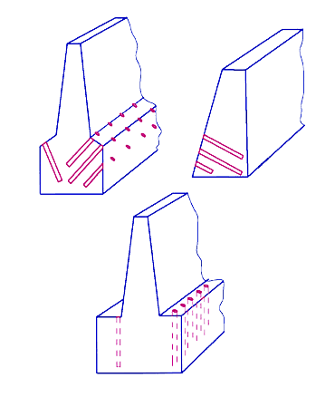
Concrete |
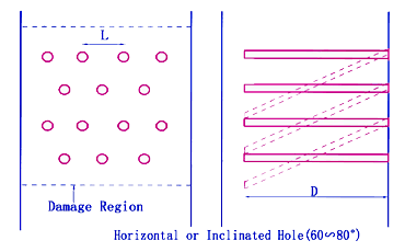
When vertical
drilling is difficult, drill horizontal holes with some slope.
|
|
| d |
32-35
mm |
| 1
1/2"-1 3/4" |
L |
40-60 cm |
| 1'4"-2'
|
D |
70%
of Height |
|
|
| |
Reinforced
Concrete |
d
and L depend on both quantity of reinforced steel and shape of that.
|
|
| d |
35
mm
|
38-44
mm |
| 1
3/8" |
1
1/2"-1 3/4" |
| L |
20-25
cm
|
30-40
cm |
| 8"-10"
|
1'-1'4"
|
D |
90%
of Height |
|
|
| |
Thin
Concrete |
| d |
32-38
mm |
| 1
1/4"-1 1/2" |
| L |
25-30
cm |
| 10"-1'
|
D |
Around
Wall Thickness |
|
|
|
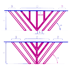
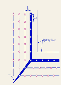
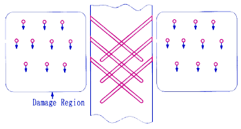
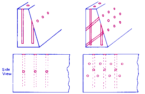
Crack
width of the front row is opened much larger than that of the behind
rows. |
| (2) Avoid
diagonal crack |
|
| d |
32-38
mm
|
|
25
mm |
32-38
mm |
| 11/4"-1
1/2" |
|
1" |
1
1/4"-1 1/2" |
| L |
25-30 cm |
|
10
cm |
10-15
cm |
| 10"-1' |
|
4" |
4"-6" |
|
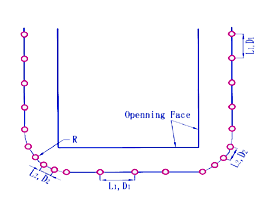
The
curvature at corner (R) should be more than 15 cm (6').
|
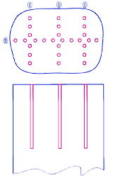
(3)
Splitting of Wall
| d |
38-44
mm |
| 1
1/4"-1 1/2" |
| L |
25-30
cm |
| 10"-1'
|
|
|
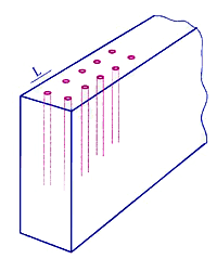
(4)
Splitting of Slab
| d |
38-44
mm |
| 1
1/2"-1 3/4" |
| L |
25-30
cm |
| 10"-1'
|
|
|
(5)
Establishment of free surfaces
| d |
38-44
mm |
| 1
1/2"-1 3/4" |
| L |
25-30
cm |
| 10"-1'
|
|
|
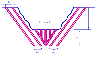
| In
stead of Burn Cut (chapter 6 of Rock), cross drilling may be used
to establish the free surface for wall case. |
|
| |
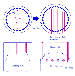
Pile
Foundation |
| d |
38-44
mm |
| 1 1/2"-1 3/4"
|
| L1 |
20 cm |
| 8" |
| L2 |
20-25 cm |
| 8"-10" |
|
|
|
| |
Mass
Concrete |
| |
Concrete
|
Reinforced
Concrete |
| d |
38-51 mm |
38-44 mm |
| 1 1/2"-2"
|
1 1/2"-1 3/4"
|
| L |
50-90 cm |
40-60 cm |
| 1'8"-3' |
1'4"-2' |
|
|
|
| |
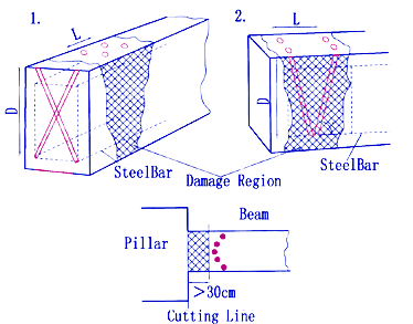
Thick
Wall |
Cracks
propagate along wall face
| d |
38-44
mm |
| 1 1/2"-1
3/4" |
| L |
30-60 cm |
| 1'-2' |
|
|
| When
perpendicular cracks to wall face are necessary: |
|
| Add
a reliever hole. Spacing may be 10 cm (4") through 20 cm (8").
|
Drill
larger d of holes |
|
| |
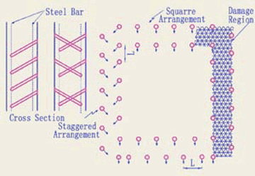
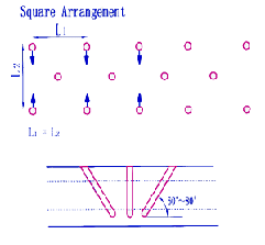
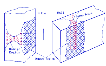
Zon Demolishing |
(1)
Stagged Arrangement (Pillar)
| d |
38-44
mm |
| 1 1/2"-1
3/4" |
| L |
20 cm |
| 8" |
| D |
20-25 cm |
| 8"-10" |
|
|
(2)
X Figure Arrangement (Pillar, Wall)
| d |
38-44
mm |
| 1 1/2"-1
3/4" |
| L |
20 cm |
| 8" |
| D |
20-25 cm |
| 8"-10" |
|
|
(3)
Cross Drilling (Beam)
| d |
38-44
mm |
| 1 1/2"-1 3/4"
|
| L |
20 cm |
| 8" |
| D |
20-25 cm |
| 8"-10" |
|
|
|
| |
Pier
Bridge Foundation |
| Drilling
depends on a shape of structure and a circumstance. |
|
|
| |
(1)
Making of large block;
Secondary breaking with large rock breaker |
|
| |
(2)
Making of small pieces;
Drilling is only from one side. |
|
|
|
| |
(3)
Wall is very high;
Vertical drilling is difficult |
|
| |
(4)
Foundation is thick,
Secondary breaking with large rock breaker. |
|
|
|
|
| |
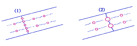
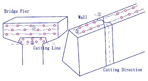
Delay
Filling |
Fill
in (1) holes then (2) holes after delaying (Refer to Figures 1,
2, and 3)) This can be applied for controlling of a crack direction
(See Bellow). |
|
|
Figure
1: Splitting of Large Boulder
| d |
38-44
mm |
| 1 1/2"-1 3/4"
|
| L |
20 cm |
| 8" |
| D |
20-25
cm 8"-10" |
|
|
| |
Reliever
holes are necessary when trench is deep |
Figure
2: Trenching and tunneling of Rock
| d |
38-51
mm |
| 1 1/2"-2"
|
| L |
30-60 cm |
| 1'-2' |
| D |
1-1.8 m |
| 3'-6' |
|
45°-60° |
|
|
| Repeat
the same procedure for deeper case |
|
|
Figure
3: Mass Concrete
| |
Concrete
|
Reinforced
Concrete |
| d |
38-51 mm |
38-44 mm |
| 1 1/2"-2"
|
1 1/2"-1
3/4" |
| L |
50-90 cm |
40-60 cm |
| 1'8"-3' |
1'4"-2' |
|
|
|
.gif)